
Assembly Instructions

ASSEMBLY INSTRUCTIONS
Planning the Installation Location
Plan the installation so that natural drainage occurs over the lower short side of the oil separator, preferably toward open air drainage such as a ditch or similar runoff area. This side functions as the drainage side of the system and should therefore not be exposed to vehicle traffic.
At the same time, plan for easy vehicle entry and exit from the opposite short side. Access can also take place from both long sides depending on the site layout.
Mark the Installation Area
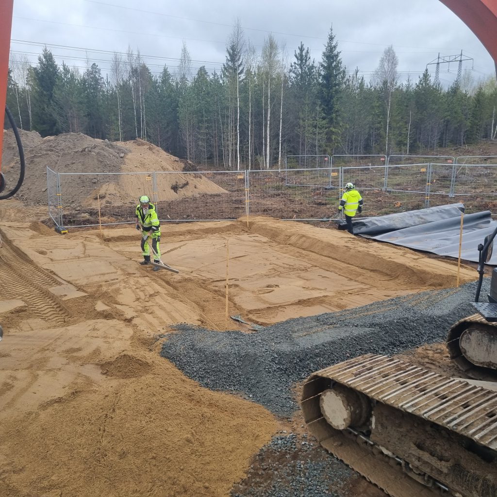
Mark the planned installation area. The oil separator itself can be used as a template to ensure correct dimensions and placement.

Prepare the Excavation
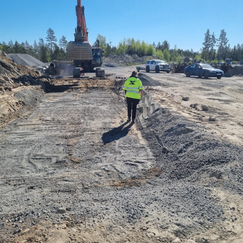
The excavation base must be completely level and horizontal without slope. This is critical to ensure proper system functionality.
The excavation should generally be approximately 40 cm below the intended finished ground level and designed with approximately 45-degree side slopes along the edges.
Position the Oil Separator
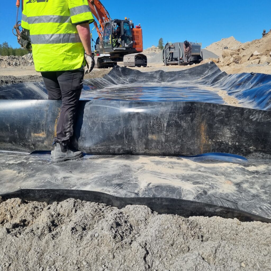
Position the oil separator with the drainage side facing the lower side of the excavation.
The oil separator should be positioned against the 45-degree slopes as follows:
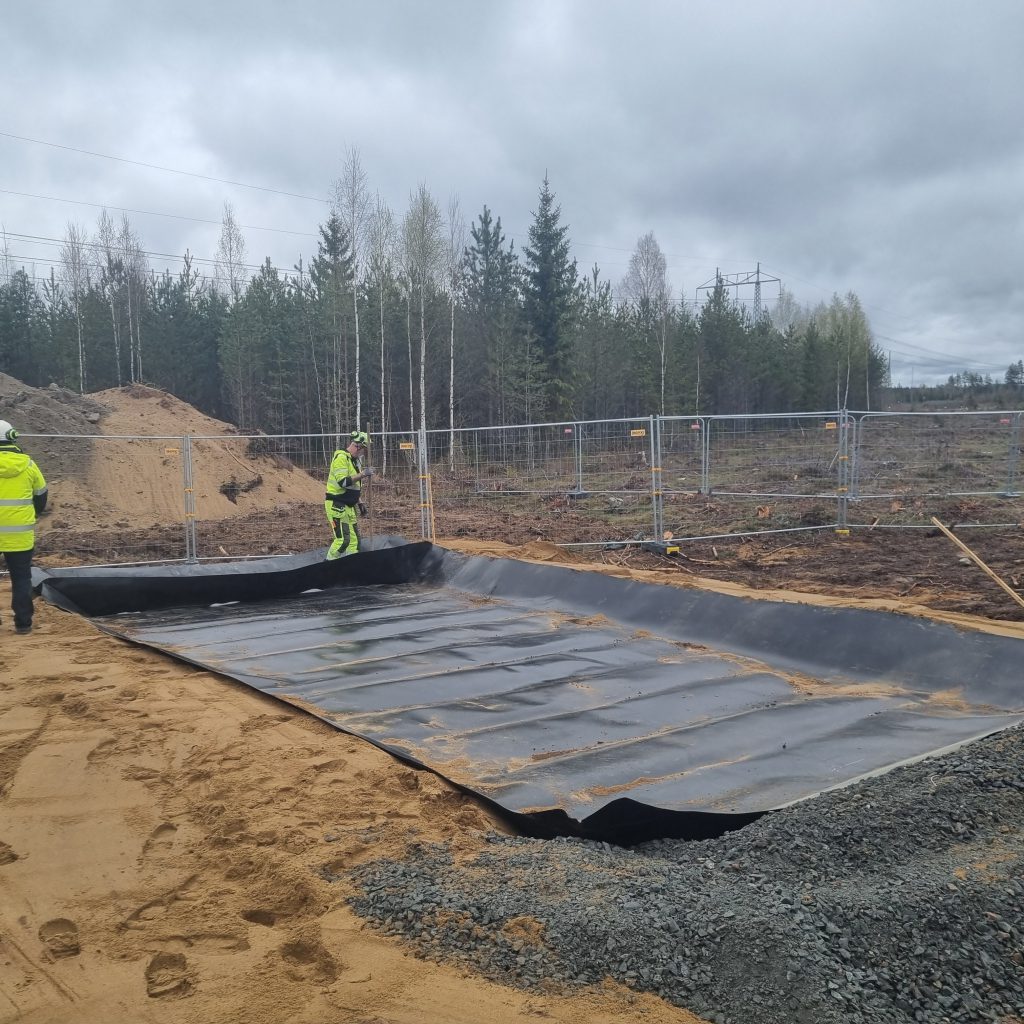
- The 45-degree fold should be approximately 55 cm from the liner edge on three sides
- On the drainage side, the 45-degree fold should be approximately 35 cm from the liner edge
Verify that the partition wall stands vertically and firmly against the base.
IMPORTANT! The entire excavation base beneath the oil separator MUST remain completely level. Any slope in the base may negatively affect function and water level control.
Backfilling Around the System
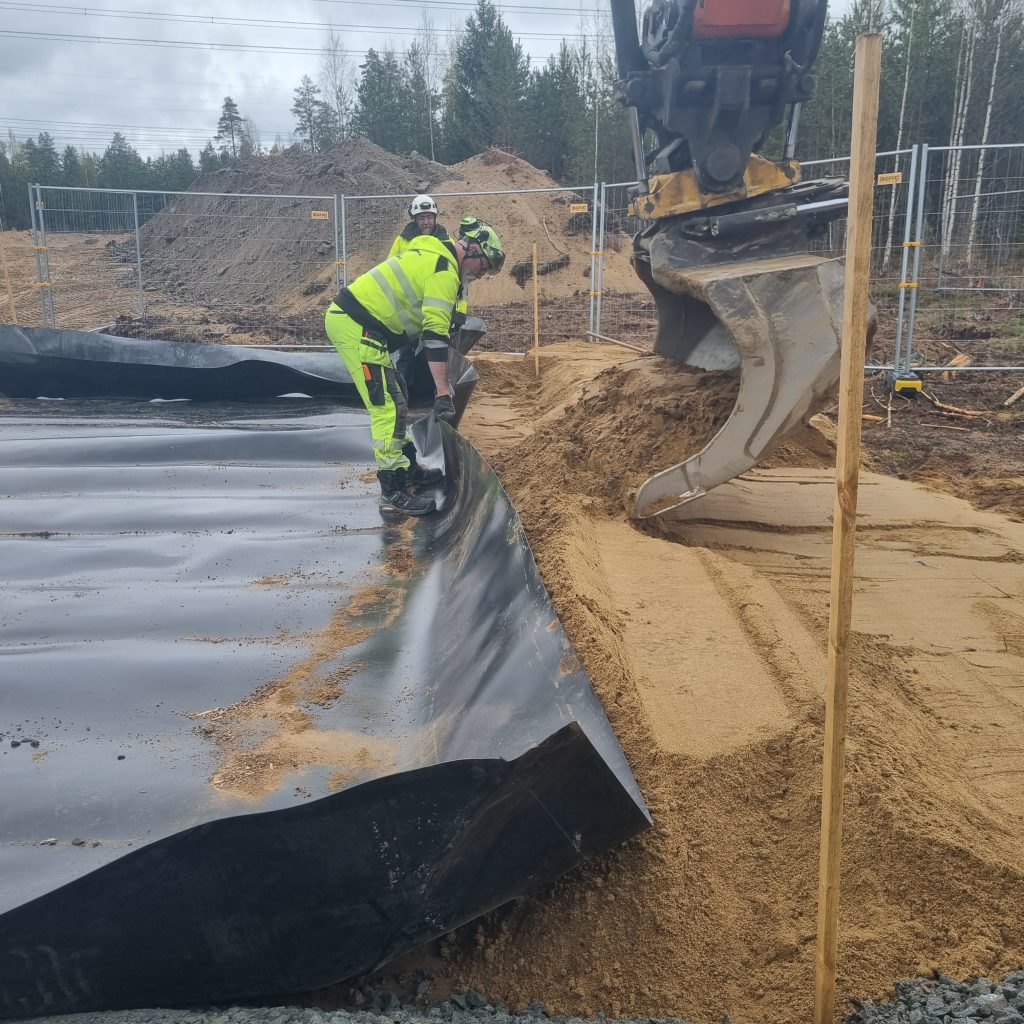
Backfill around the outside of the excavation to create stable 45-degree slopes surrounding the oil separator.
The three elevated sides are typically built up to approximately 40 cm above the excavation base, while the lower drainage side is built up to approximately 25 cm.
Building the Gravel Base Layer
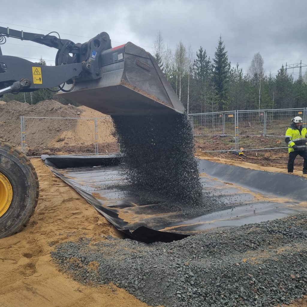
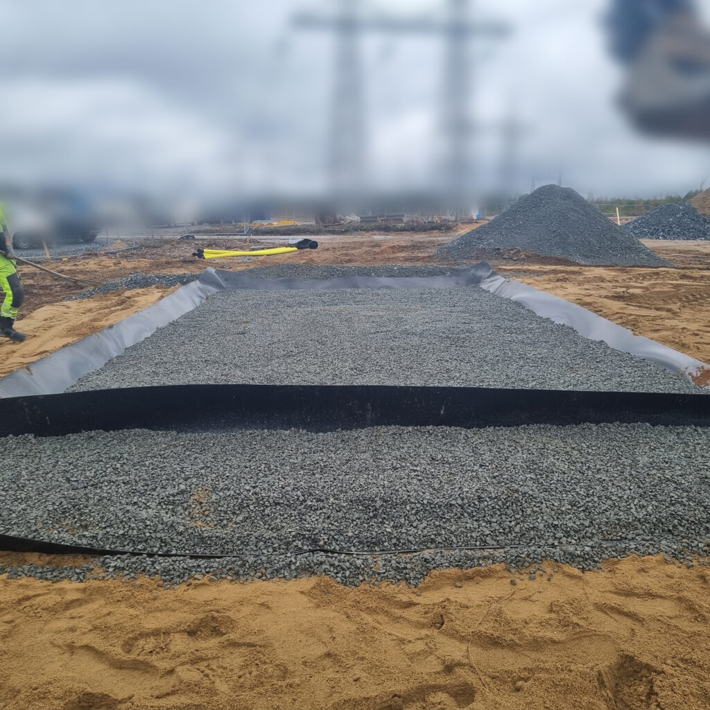
Fill the entire oil separator with a gravel layer, for example 8–16 or 16–32 aggregate, to a thickness of approximately 20–25 cm.
The gravel layer should be built up to the height of the drainage side.
Final Filling and Finished Surface
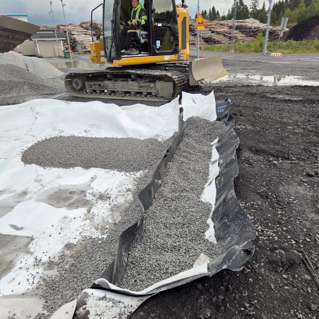
Complete the filling of the oil separator using load-bearing and permeable material such as:
- 0–16
- 0–32
- gravel
The drainage side should simultaneously be supported with gravel according to the recommended design.
The finished surface above the oil separator should remain level with the surrounding terrain to allow safe vehicle entry and exit without placing excessive load on or damaging the structure.
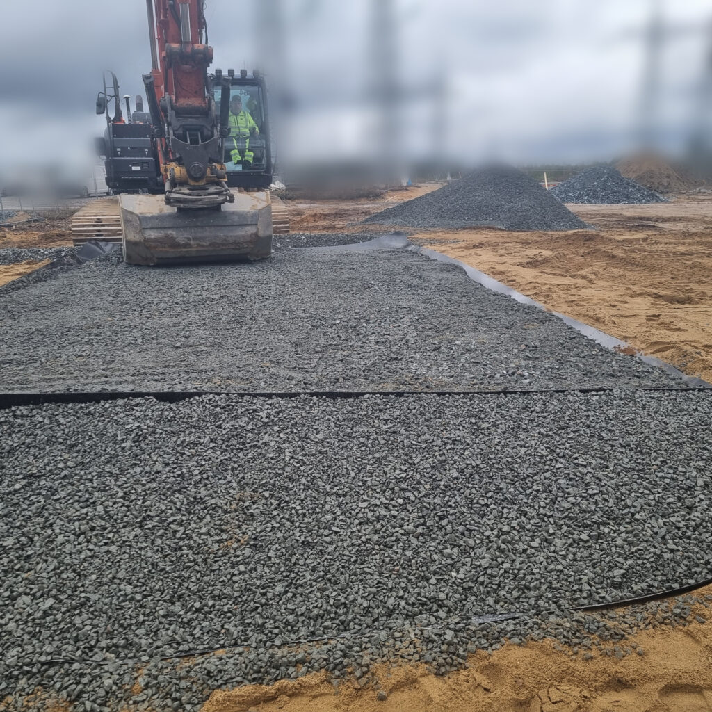
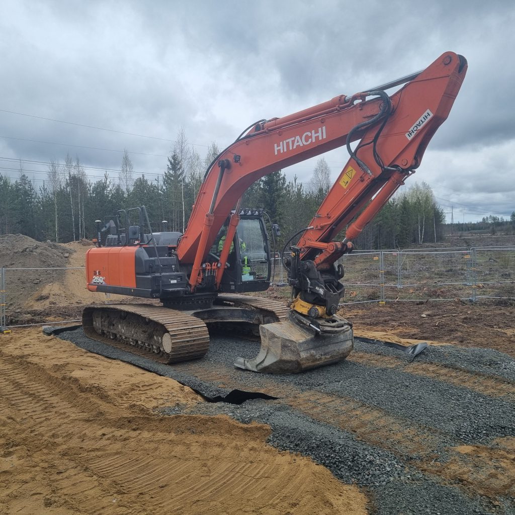
Finished 8m
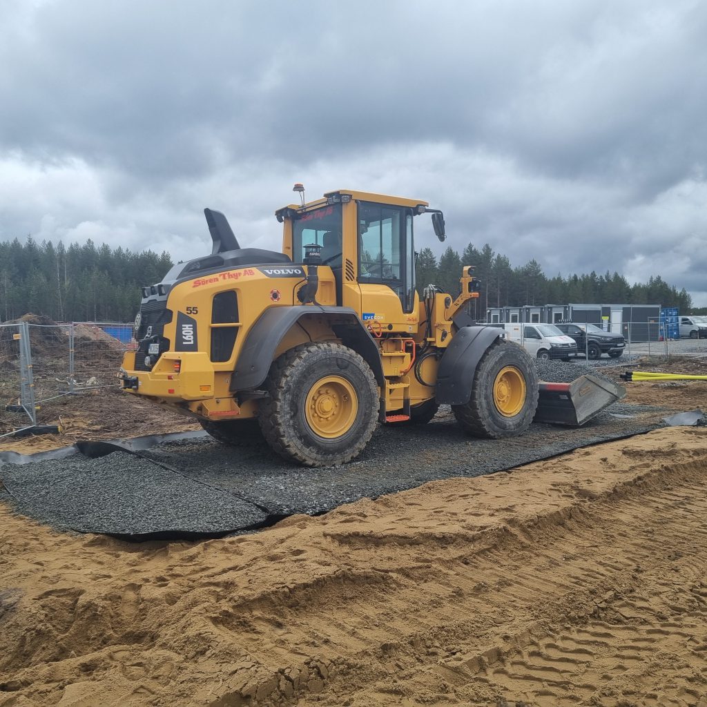
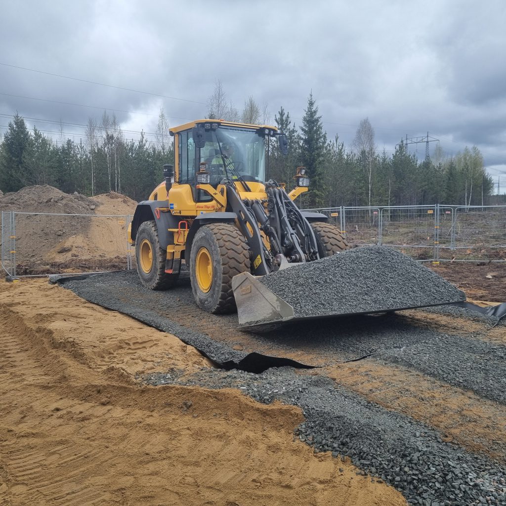
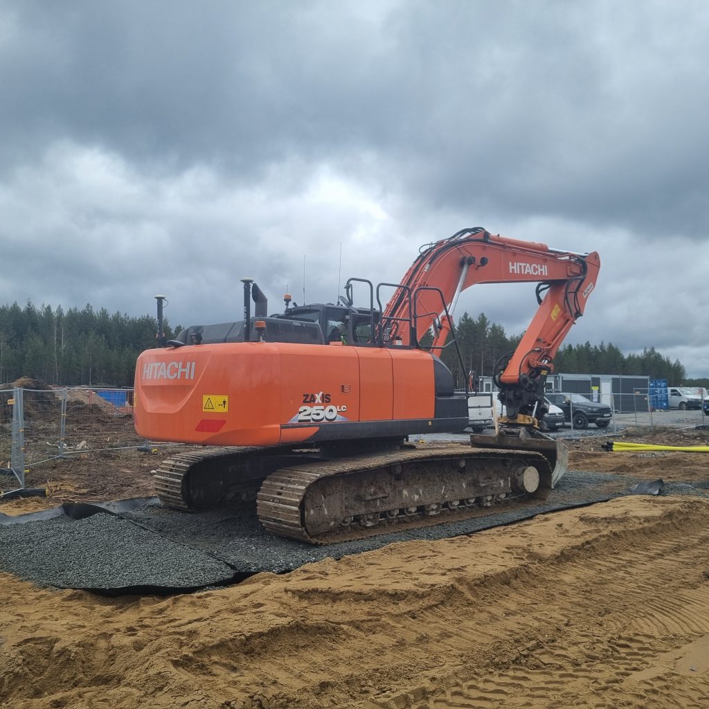
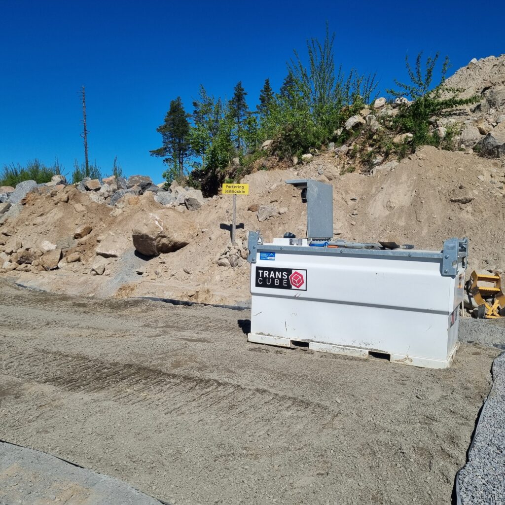
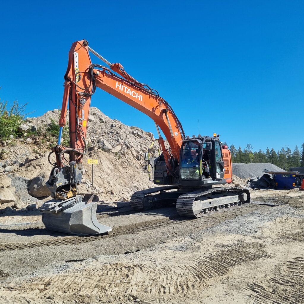
Finished 12m

Additional Information
- When gravel is used in the lower section of the oil separator, the system can retain approximately 2000–2500 liters of oil or diesel without leakage
- The oil separator is manufactured from 1.5 mm oil-resistant HDPE plastic
- Since the system continuously separates and drains water, roof structures are normally unnecessary during rainfall
- If oil or diesel contamination is detected, contaminated material must immediately be removed and handled according to applicable waste and environmental requirements. New material should then be refilled
- The product is protected by a Swedish patent approved in 2025
- Installation normally does not require a building permit, but local regulations and site conditions should always be verified before installation
Diagram 8m

Diagram12m
